Look at the Gnôme 9N Rotary Engine
(ALSO KNOWN AS THE GNÔME MONOSOUPAPE)
by Fred Murrin &Terry Phillips
(Article reproduced with permission of the author)
(ALSO KNOWN AS THE GNÔME MONOSOUPAPE)
by Fred Murrin &Terry Phillips
(Article reproduced with permission of the author)
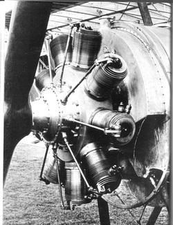
The Gnôme “single valve” (translation of Monosoupape) engine has made its mark in aviation history mainly as the engine that powered the Nieuport 28 and which, to a lesser extent, was used in some Sopwith F.1 Camels, occasionally in the Avro 504, and sometimes in the Morane-Saulnier A. 1, and with at least one example powering the Hanriot HD-1.
The Gnôme engine has captured the imagination of many casual readers of the Great War era for decades and the folklore surrounding its operation includes some of the most enduring misconceptions about WW1 aviation.
This is a detailed explanation about the design of the Gnôme 9N and some comparisons to its predecessor, the Gnôme Omega 50 horsepower (h.p.) engine of 1909. Many people are under the impression that all Gnôme engines were of the single valve variety. In fact, the early Gnôme Greek letter engines like the Omega had a troublesome automatic intake valve in the piston in addition to the pushrod operated exhaust valve. Only the later Gnôme engines were true monosoupapes. Gnôme monosoupapes included engines with seven to eighteen cylinders and horsepower ratings from 80-240 h.p., but only the 100 h.p. type B9 and 160 h.p. type N Gnômes saw wide service.
In the earlier Gnômes, the induction valve was placed in the crown of the piston and was not actuated by a pushrod or cam. It was an “atmospheric” valve, in the vernacular of the times, meaning that it was merely sucked open by the vacuum created as the piston traveled downward in the cylinder. Atmospheric valves were a common practice in early aero engines and began with the engine on the Wright Flyer of 1903 (although not in the piston).
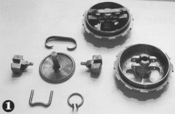
Photo 1 shows an induction valve arrangement for a Gnôme Omega. The springs aided in closing the valve when the piston reached bottom dead center and the two counterweights offset the weight of the valve so the effects of centrifugal force were neutralized. Remember, this is critical in a rotating engine where centrifugal force would tend to pull the induction valve outward, or in this case, open. This ensured the springs could more easily do their job of pulling the valve closed when the piston reached bottom dead center.
The atmospheric valves proved to be a maintenance headache, however, and the Gnôme design staff looked for ways, to improve an otherwise reliable design. The idea of transfer ports at the base of the cylinders seemed simple enough, but keeping the engine as a conventional Otto-cycle design would require more creative thinking. The answer was eventually to be found in the design of the cam profile.
The single valve design has led some people to assume the Gnômes were a two-cycle design, which they were not. The fact that monosoupapes did not utilize a carburetor caused many people to assume the engines ran at full speed and the only way to control engine speed was by using the proverbial “blip” switch. This is partially true with the 100 h.p. Gnôme. Pilots were taught to reduce engine speed by leaning out the mixture with the fine mixture control valve in addition to using the “blip” switch as necessary. This was not successful, however, as the lean mixture and typically short travel of the exhaust valve caused the valves to burn in a short time. Leaning out the mixture inside the crankcase also created a fire hazard. The threat was not that the airplane might catch fire, rather that the engine could not be re-started until the fire inside burnt itself out, which could take several precious seconds. A fire would require the pilot to shut off the fuel, keep the nose down in order to keep the engine “wind-milling”, then turn the fuel on once the fire was out. Assuming the fire was completely out, which was often difficult for the pilot to tell, the engine would resume running once again. This was providing, of course, he had enough altitude to make all of this happen.
Many historians have wondered why the 100 h.p. Gnôme and the 160 h.p. Gnôme did not use carburetors when earlier designs did. The following description of the four cycles of the single-valve design will make the answer more clear.
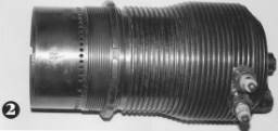
The transfer ports, which were a row of holes drilled near the base of the cylinder (see Photo 2), were the interface between the air/fuel mixture inside the crankcase and the inside of the cylinder where combustion would take place. The challenge was to ensure the exploded charge inside the cylinder was expelled before the ports were exposed at the end of the power stroke, or bottom dead center.
This was accomplished by opening the exhaust valve at 100 degrees after top dead center on the power stroke, when the piston had traveled just over half way down the cylinder. The lower octane gasoline used in 1918 burned much faster than higher octane gasoline does today and the charge was likely combusted by the time the valve began to open.
The valve remained open as the piston traveled beyond the transfer ports to bottom dead center. Since the charge had finished burning and was largely expelled or neutralized, there was little chance of igniting the mixture inside the crankcase. As the piston traveled upward on the exhaust stroke, there was actually little left to exhaust.
In the event the charge was not completely burnt or expelled by the time the transfer ports were exposed, the engineers had developed a unique solution to keep the air/fuel mixture inside the crankcase from igniting. That mixture was too rich (too much fuel and not enough air) for combustion and therefore the crankcase mixture would not ignite if the charge in the cylinder continued to burn after the ports were exposed.
In order to lean out the air/fuel mixture from the crankcase so it could ignite successfully in the combustion chamber, the exhaust valve would remain open as the piston started descending in the cylinder on the induction stroke (the valve remaining open after the exhaust stroke). By doing this, fresh air was drawn into the cylinder through the exhaust valve. The exhaust valve remains open throughout most of the induction stroke until just before the transfer ports are exposed. It closes as the piston continues traveling downward thereby creating a partial vacuum in the combustion chamber. When the transfer ports are finally exposed, there is a suction of the extra rich mixture from the crank-case into the cylinder to mix with the fresh air already there and these combined to make the correct ratio for combustion.
Since most of the fresh air is drawn into the combustion chamber through the exhaust valve, there is insufficient vacuum through the hollow crankshaft (the normal mounting position of a carburetor on a rotary engine) to draw fuel into the crankcase.
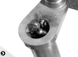
The fuel traveled from the fuel tank to the “Tampier” valve, or fine mixture control valve, to an inlet in the crankshaft and along a copper tube to a spray nozzle situated just inside the crankcase (see Photo 3).
It is likely that the 100 h.p. Gnôme was rushed into service without having a better way to control revolutions per minute (RPM) other than to lean it out and use the “blip” switch.
As the Gnôme engineers progressed to building a more powerful engine, it was necessary to come up with a better solution for RPM control than the inadequate method used on the 100 h.p. engine. This resulted in the ingenious invention of the selector switch that was used on the 9N series (160 h.p.).
If the old axiom is true that “simple is better”, then the evolution of the Gnôme 9N epitomizes this notion. Based on the 100 h.p. platform, it is the simplest and therefore most reliable of the rotary engine designs. Compared to other rotary engines of the period, the 9N had half as many push rods (except for the single pushrod Le Rhone), half as many lifters and half as many valves.
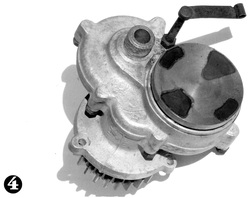
RPM was controlled by means of a selector switch that connected to the drive unit on the back of the engine and ran off of the accessory drive gear (see Photo 4). This unit simply grounded out the magneto at regular intervals to prevent an impulse from going to the spark plug. This device is one of the most misunderstood technologies stemming from WWI aircraft engines. Even to this day, people talk about the selector switch cutting out 1 or 3 or 5 cylinders in order to reduce RPM, which is not the way the selector switch worked. That would be paramount to removing 1 or more spark plug wires from your car engine and then driving it. One can imagine how bad such an arrangement would shake and vibrate. The authors are of the opinion that this misconception may have arisen from poorly written instructions in a 27th Aero Squadron document on the subject.
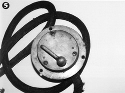
In order to keep the engine running smoothly on reduced power settings, it was necessary for the selector switch to cut out all cylinders at evenly spaced intervals. It was also beneficial to have all cylinders firing periodically to keep them warm and to prevent the spark plugs from fouling with oil. The selector switch has five positions, zero (0) for off and four running positions, one through four (1-4) (see Photo 5). The Gnôme 9N had two magnetos (and two spark plugs per cylinder) and the selector switch was wired to the right magneto only, so it was necessary for the pilot to turn off the left magneto if he wanted to change the speed of the engine. It was not wired to both magnetos in order to keep them separate and redundant.
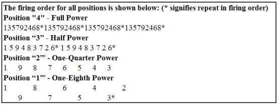
When set on position “4”, there was no interruption of the magneto impulses and all cylinders fired in their regular four-cycle rotation. When set on position “3”, every other impulse from the magneto was prevented, causing each cylinder to fire once every eight cycles instead of every four. When set on position”2”, three out of four impulses from the magneto were prevented, causing each cylinder to fire once every sixteen cycles. When moved to position “1”, seven out of eight impulses from the magneto were prevented, causing each cylinder to fire once every thirty-two cycles.
In this way, the intervals between impulses were regular, which allowed the engine to run smoothly at reduced power settings with all cylinders still firing-just not as often as at full speed.
The “blip” switch was attached to the same magneto to which the selector switch was wired. The four positions were sufficient for just about anything the pilot wanted to do from taxiing and patrolling to descending and gliding in for a landing. The “blip” switch was there just in case the pilot needed it for anything over and above what the selector would provide, which would be letting the engine coast while the button was depressed. The left magneto was turned on during the take off roll, after the selector switch was advanced to position 4, to augment the right magneto and establish redundancy. If the pilot wanted anything other than full power, he would turn off the left magneto because it would always keep the engine running at full speed, and then use the selector magneto only.
The use of the “blip” switch was discouraged because it was hard on the crankshaft, especially when blipping from full power. The crankshaft is indexed to the mounting plate by a single key and the engine’s tremendous torque would occasionally shear the key by us of the “blip” switch at high power settings. This would damage the crankshaft and destroy the engine mounting plate. Harold Hartney once wrote that the “blip” switch was almost not necessary when operating the Gnôme 9N.
The advantage to the selector switch arrangement was that once the fine mixture control valve was set, the pilot did not have to change it for different power settings, unlike the other rotaries where both the carburetor air slide and fine mixture control valves had to be adjusted in harmony for different power settings. This made air fighting a little less complicated. It should be noted that some modern day operators of these engines connect the “blip” switch to the left magneto and turn off the right (selector) magneto for taxi and landing, choosing to rely entirely on the “blip” switch for speed control. For reasons previously stated, this is not the recommended method and the description above represents the engineer’s design intent for using the selector switch and operating the Gnôme 9N with care.